Mako 5600
Quick Start Guide
Box Contents
Mako 5600-LTE / Mako 5600-LTE US models:
One (1) Mako 5600-LTE or Mako 5600-LTE US device
Two (2) LTE antennas
Two (2) Ethernet patch cables
Three (3) mounting brackets: T-Rail, wall-mount, and wire-hold
One (1) mounting screw set
Mako 5600-5G model:
One (1) Mako 5600-5G device
Four (4) 5G antennas
Two (2) Ethernet patch cables
Three (3) mounting brackets: T-Rail, wall-mount, and wire-hold
One (1) mounting screw set
Requirements
You must have:
Broadband internet connectivity
Electric power via either Power over Ethernet (PoE) or a power outlet
NOTE: power supply sold separately
Recommendations
You may want:
A surge protector when connecting to a power outlet
One or more Ethernet switches and additional Ethernet cables
An internet-connected device with a modern web browser for remote management
Important Safety Instructions
Avoiding Fire, Shock, Electrical Damage
Keep your Mako device away from water or damp environments, including wet basements and around refrigeration units. Do not place containers of fluid on the Mako device, such as drinks, vases or cleaning products.
Do not attempt to open the Mako device. There are no user-serviceable parts. Repairs may only be performed by accredited service personnel.
Observe all warnings affixed to this Mako device or its power supply.
Use surge protectors to mitigate interference and damage from lightning storms.
Password Security
Protect your credentials. Do not write your password down or give it to anyone else, not even to Mako Support personnel or sanctioned Managed Service Providers. They will never ask for your password. On rare occasions the Mako ID may be requested. The Mako ID is printed on the back of each Mako device.
Connecting Your Mako Device
1. Attach External Antennas
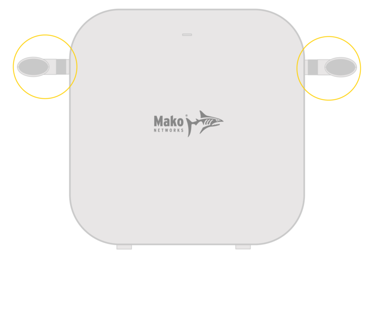
LTE Antennas
Mako 5600-LTE and Mako 5600-LTE US
The Mako 5600-LTE and Mako 5600-LTE US come with two LTE antennas. Attach these antennas to the Mako device as shown.
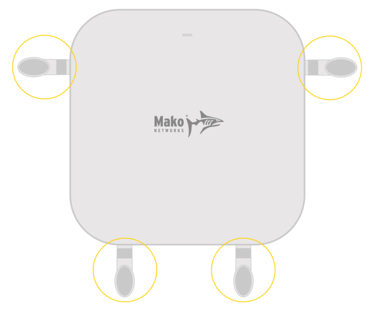
5G Antennas
Mako 5600-5G
The Mako 5600-5G comes with four 5G antennas. Attach these antennas to the Mako device as shown.
2. Connect WAN Port to Your Broadband Modem (Optional)

LAN 4 (WAN 2) Port
PoE
To deploy your Mako 5600 device as a security gateway using PoE, connect its LAN 4 port to your broadband modem.
NOTE: LAN 4 must be converted to WAN 2 in the Mako CMS to deploy in this configuration (see Step 5).
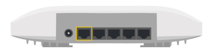
WAN Port
Power Outlet
To deploy your Mako 5600 device as a security gateway using a power outlet, connect its WAN port to your broadband modem.
NOTE: you will need to purchase a power supply from Mako Networks to deploy in this configuration.
3. Connect LAN Ports to Your Local Network
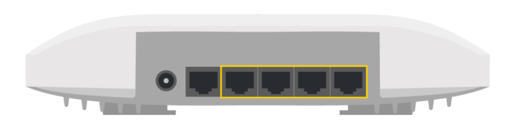
LAN 1, LAN 2, LAN 3, and LAN 4 Ports
Use the LAN ports to connect to your local network, as needed.
NOTE: if the WAN port is in use for PoE and WAN connectivity is needed, the LAN 4 port can be used for WAN instead of LAN (see Step 5).
4. Connect to Power
WAN (PoE) Port
PoE
To use PoE to power your Mako 5600 device, its WAN port must be connected to a PoE port on another device that can provide power, such as a Mako Managed Switch.
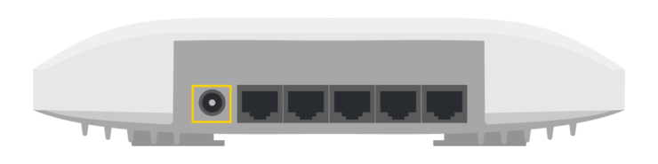
DC12V Port
Power Outlet
If you are not using PoE, you must purchase a power supply from Mako Networks to connect your Mako 5600 device’s DC12V port to a power outlet.
5. Log In to the Mako CMS (Optional)
Your Mako device gets its configuration from the Mako Central Management System (CMS). Your Mako Networks reseller should have preconfigured a profile for your Mako device in the Mako CMS and should also have provided you with login credentials to access the Mako CMS to control and manage your Mako device.
The Mako CMS can be accessed by clicking the “Login” link at:
In the Mako CMS, you can verify that important network settings are correct, such as your Wi-Fi and cellular configurations.
NOTE: if you need to deploy this Mako device using both PoE and WAN connectivity, you must convert LAN 4 to WAN 2 in the Mako CMS. This may have been preconfigured by your Mako Networks reseller.
Regulatory Statements
FCC Compliance Notice
Any changes or modifications not expressly approved by the party responsible for compliance could void your authority to operate the equipment.
RF Exposure Statements
- This Transmitter must not be co‐located or operating in conjunction with any other antenna or transmitter.
- This equipment complies with FCC RF radiation exposure limits set forth for an uncontrolled environment. This equipment should be installed and operated with a minimum distance of 20 centimeters between the radiator and your body or nearby persons.
Note: This equipment has been tested and found to comply with the limits for a Class B digital device, pursuant to part 15 of the FCC Rules. These limits are designed to provide reasonable protection against harmful interference in a residential installation.
This equipment generates, uses and can radiate radio frequency energy and, if not installed and used in accordance with the instructions, may case harmful interference to radio communications. However, there is no guarantee that interference will not occur in a particular installation. If this equipment does cause harmful interference to radio or television reception, which can be determined by turning the equipment off and on, the user is encouraged to try to correct the interference by one or more of the following measures:
- Reorient or relocate the receiving antenna.
- Increase the separation between the equipment and receiver.
- Connect the equipment to an outlet on a circuit different from that to which the receiver is connected.
- Consult the dealer or an experienced radio/TV technician for help.
![]()
HAVE QUESTIONS?
CONTACT SUPPORT
Mako Networks
1355 N McLean Blvd
Elgin IL 60123
USA
US +1 800 851 4691, opt. 1
UK +44 2037 693368
NZ +64 9 448 1340
AU +61 2 8073 4474
© Copyright 2024 Mako Networks Ltd.
All Rights Reserved.